SPARX: An Open-Source, Automated, Programmatically Generated, Frequency-Scalable Six-Port Receiver in 130-nm CMOS

This documentation is a Work in Progress.
This repository requires the IIC-OSIC-TOOLS container with tag 2026.05 or later.
1 Overview
SPARX stands for Six-Port Automated Receiver. The complete layout is generated in Python using self-made RF devices as a GDSFactory IHP PDK add-on. S-parameter simulation of the passive RF structures is performed with AWS Palace. With KLayout, Magic, and Netgen, a complete LVS, DRC, and RCX verification flow is implemented. The SBD-based power detector is designed in Xschem and simulated with ngspice and VACASK. This repository is controlled by a Makefile. Just clone it and run make all to build the six-port receiver at 160 GHz and verify the power detector cell. To generate a frequency-scalable layout at a different target frequency, for example 77 GHz, run make build-layout FREQ=77.
Index Terms: Branch-line coupler, frequency-scalable layout, GDSFactory, hairpin coupled-line bandpass filter, IHP Open-PDK, mmWave, open-source EDA, power detector, programmatic layout, Schottky barrier diode, six-port receiver, Wilkinson power divider.
2 References
To understand the principle of six-port receivers and their architectures, it is recommended to read the following references:
- A. Koelpin, G. Vinci, B. Laemmle, D. Kissinger and R. Weigel, “The Six-Port in Modern Society,” in IEEE Microwave Magazine, vol. 11, no. 7, pp. 35–43, Dec. 2010, doi: 10.1109/MMM.2010.938584
- T. Hentschel, “The six-port as a communications receiver,” in IEEE Transactions on Microwave Theory and Techniques, vol. 53, no. 3, pp. 1039–1047, March 2005, doi: 10.1109/TMTT.2005.843507
- M. Mailand, “System Analysis of Six-Port-Based RF-Receivers,” in IEEE Transactions on Circuits and Systems I: Regular Papers, vol. 65, no. 1, pp. 319–330, Jan. 2018, doi: 10.1109/TCSI.2017.2734922
3 Requirements
To build this six-port receiver, the following tools and their respective dependencies are required:
- GDSFactory: https://github.com/gdsfactory/gdsfactory
- Updated IHP-Open-PDK GDSFactory version: https://github.com/iic-jku/IHP/tree/IHP-TO
- IHP-Open-PDK: https://github.com/iic-jku/IHP-Open-PDK
The updated IHP-Open-PDK GDSFactory version contains all self-made RF devices and wraps existing PCells provided by the IHP-Open-PDK, allowing them to be used directly within the GDSFactory framework. This approach requires very little maintenance: if IHP changes the layout of a cell, no wrapper update is necessary — only interface changes to a PCell function require updates.
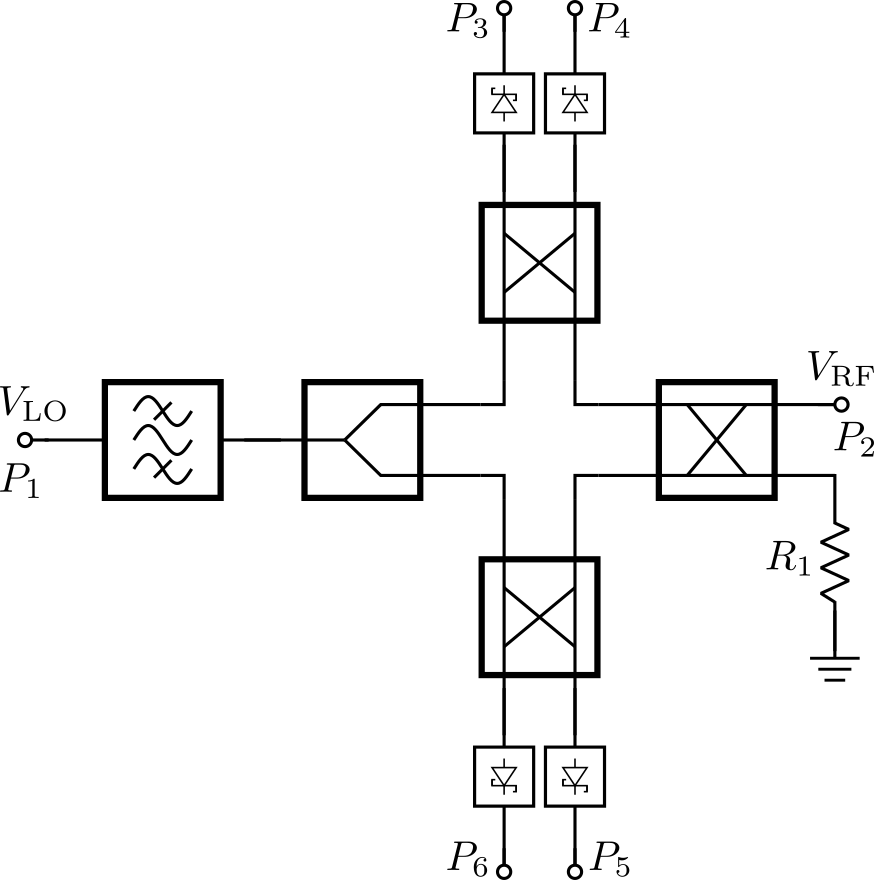
4 Block Diagram
The SPARX architecture consists of the following main components:
- Six-Port
- Branch Line Coupler (BLC)
- Wilkinson Power Divider (WPD)
- Hairpin Coupled-Line Bandpass Filter (BPF)
- Power Detector (PD)
- Schottky Barrier Diode (SBD)
- Metal Stack
- TopMetal2 (TM2): RF traces
- Metal5 (M5): GND plane
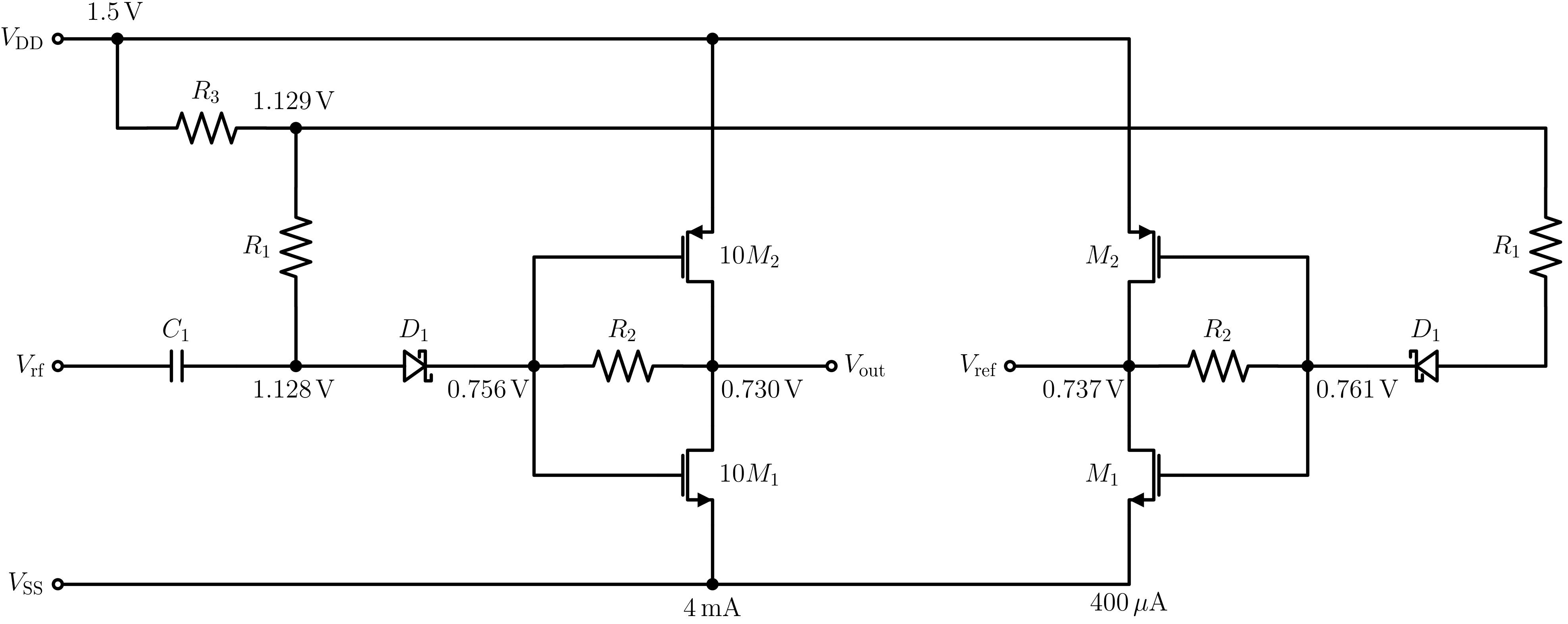
5 SBD-based Power Detector
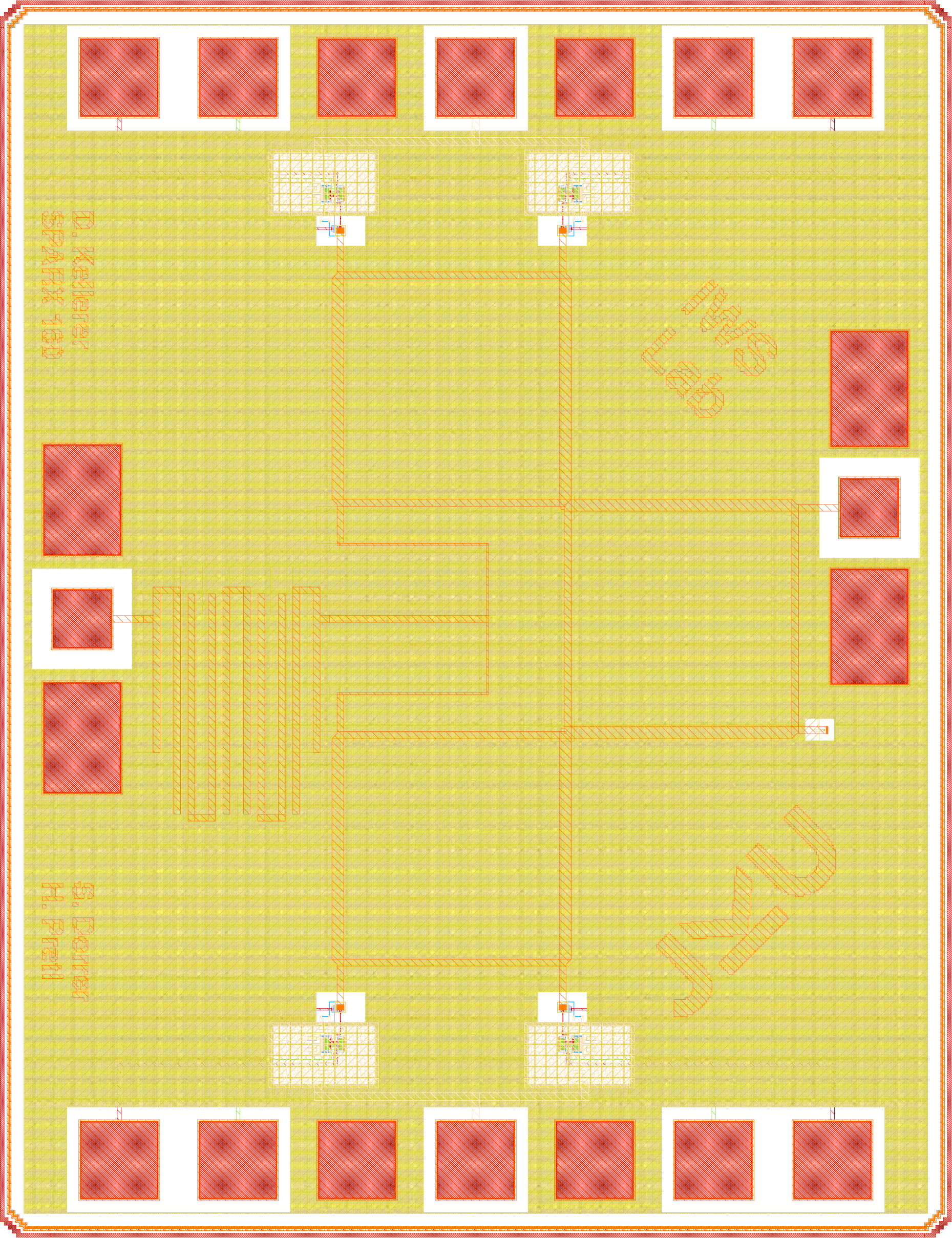
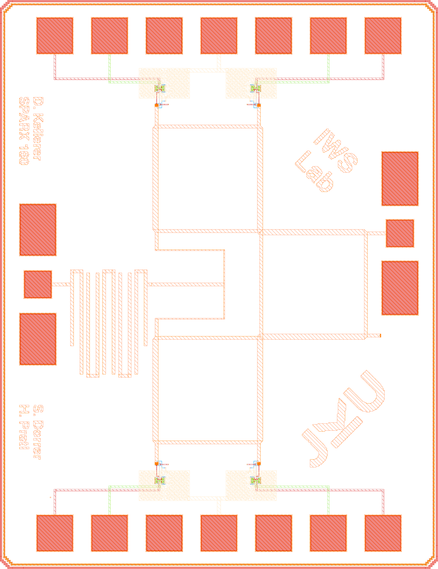
6 Layouts
The following figures show the chip layout of the 160 GHz six-port receiver (die area: 1000 × 1400 µm).
| Parameter | Value |
|---|---|
| Technology | IHP SG13G2 (130 nm CMOS) |
| Die Area | 1000 × 1400 µm (1.4 mm²) |
| Supply Voltage | 1.5 V |
7 Acknowledgements
This project is funded by the JKU/SAL IWS Lab, a collaboration of Johannes Kepler University and Silicon Austria Labs.

|
|