Analog (Integrated) Circuit Design
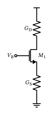
Figure 42: A MOSFET cascode circuit.
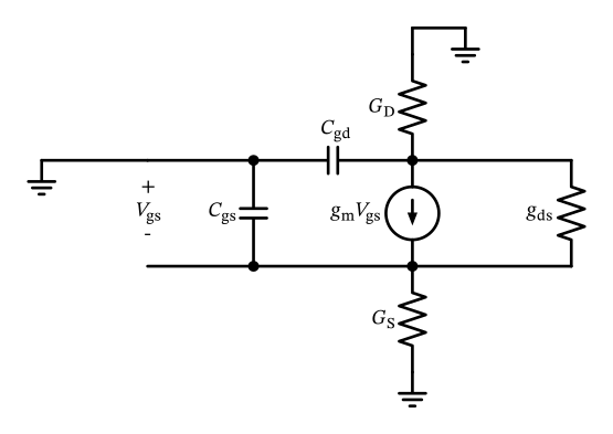
Figure 43: The MOSFET cascode small-signal model.
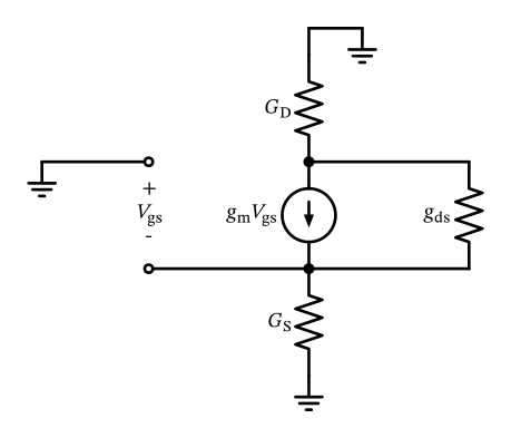
Figure 44: The simplified MOSFET cascode small-signal model.
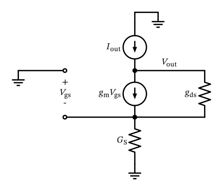
Figure 45: The simplified MOSFET cascode small-signal model for calculation of the output impedance.
We realize that \(I_\mathrm{out}\) flows through \(G_\mathrm{S}\) (as there is no other way to go) and drops \(V_\mathrm{gs}\) (note the sign): \[ V_\mathrm{gs}= -\frac{I_\mathrm{out}}{G_\mathrm{S}} \]
Calculating KCL at the output node results in \[ I_\mathrm{out} - g_\mathrm{m}V_\mathrm{gs}- g_\mathrm{ds}V_\mathrm{ds}= 0. \]
Using the previously found identities, and after a bit of algebraic manipulations we arrive at \[ g_\mathrm{out} = \frac{I_\mathrm{out}}{V_\mathrm{out}} = \frac{g_\mathrm{ds}}{1 + \frac{g_\mathrm{m}+ g_\mathrm{ds}}{G_\mathrm{S}}} = \frac{g_\mathrm{ds}\cdot G_\mathrm{S}}{G_\mathrm{S} + g_\mathrm{m}+ g_\mathrm{ds}} \tag{34}\]
We can further calculate the benefits of a cascode if we assume we put a cascode on top of a common-source transistor stage (thus \(G_\mathrm{S} = g_\mathrm{ds}'\)) and get \[ g_\mathrm{out} = \frac{g_\mathrm{ds}\cdot g_\mathrm{ds}'}{g_\mathrm{ds}' + g_\mathrm{m}+ g_\mathrm{ds}} \approx g_\mathrm{ds}' \frac{g_\mathrm{ds}}{g_\mathrm{m}} \tag{35}\]
Benefit of Cascode (Output)
The output impedance of the lower MOSFET (\(r_\mathrm{out} = 1 / g_\mathrm{ds}'\)) is increased by the self-gain (\(g_\mathrm{m}/ g_\mathrm{ds}\)) of the cascode transistor! This is a powerful technique to increase the output impedance of a transistor stage by cascoding, much better than increasing \(L\)!
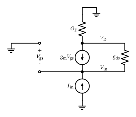
Figure 46: The simplified MOSFET cascode small-signal model for calculation of the input impedance.
Formulating KCL at the input node results in \[ I_\mathrm{in} + g_\mathrm{ds}V_\mathrm{ds}+ g_\mathrm{m}V_\mathrm{gs}= 0. \]
After some manipulation we find that \[ g_\mathrm{in} = \frac{I_\mathrm{in}}{V_\mathrm{in}} = \frac{(g_\mathrm{m}+ g_\mathrm{ds}) \cdot G_\mathrm{D}}{g_\mathrm{ds}+ G_\mathrm{D}}. \tag{36}\]
\[ g_\mathrm{in} = g_\mathrm{m}+ g_\mathrm{ds}\approx g_\mathrm{m}, \]
Benefit of Cascode (Input)
This has the practical benefit that a capacitance connected at this node results in a high-frequency pole, which is often not critical in terms of stability. Further, the voltage swing at a cascode input node is small due to the often small impedance, and this minimizes the Miller effect at connected inter-node capacitors (see Section 17.1).