Appendix: Useful Circuit Theorems
Analog (Integrated) Circuit Design
17 Appendix: Useful Circuit Theorems
17.1 Miller’s Theorem
Miller’s Theorem
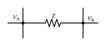
Figure 82: An impedance connected between two nodes A and B.
Miller’s Theorem
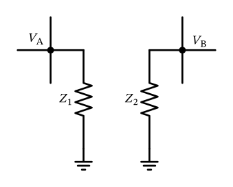
Figure 83: An equivalent circuit using Miller’s theorem.
Miller’s Theorem
Using Miller’s theorem (Sheikholeslami 2015) we can calculate \[ Z_1 = \frac{Z}{1 - A} = \frac{Z}{1 - V_\mathrm{B} / V_\mathrm{A}} \] and \[ Z_2 = \frac{Z}{1 - A^{-1}} = \frac{Z}{1 - V_\mathrm{A} / V_\mathrm{B}} \] to arrive at an equivalent circuit, given that \(A = V_\mathrm{B} / V_\mathrm{A}\) is the voltage gain between nodes A and B.
Miller’s Theorem
Miller’s Secret
Note that Miller’s compensation is so much more than just making a big capacitor out of a small one. There are layers upon layers of subtlety, and huge hidden benefits which can be read in (Mangelsdorf 2025a) and (Mangelsdorf 2025b).
17.2 Bode’s Noise Theorem
Bode’s Noise Theorem
\[ \overline{V_\mathrm{n}^2} = kT \left( \frac{1}{C_\infty} - \frac{1}{C_0} \right), \]