Power Amplifiers

Radio-Frequency Integrated Circuits

8 Power Amplifiers

Power Amplifiers

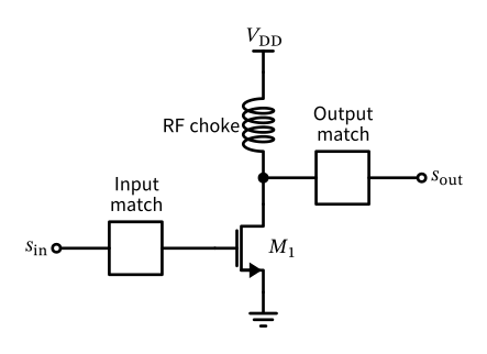
Figure 99: A basic single stage single-ended common-source power amplifier with input and output matching.

Power Amplifiers
\[ P_\mathrm{out,max} = \frac{V_\mathrm{DD}^2}{2 R_\mathrm{L}}. \]

Power Amplifiers

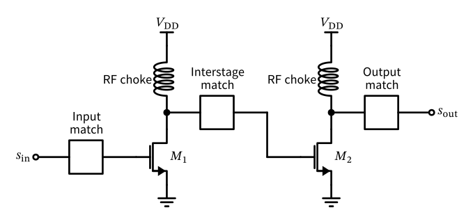
Figure 100: A basic two-stage single-ended common-source power amplifier with input and output matching.

8.1 PA Efficiency

PA Efficiency

\[ \eta = \frac{P_\mathrm{out}}{P_\mathrm{dc}} \]

\[ \text{PAE} = \frac{P_\mathrm{out} - P_\mathrm{in}}{P_\mathrm{dc}} \]

8.2 PA Nonlinearity

PA Nonlinearity

\[ y(t) = A[r(t)] \cos\{ \omega_0 t + \psi(t) + \varphi[r(t)] \} \]

\[ A(r) = \frac{\alpha_1 r}{1 + \beta_1 r^2} \quad \text{and} \quad \varphi(r) = \frac{\alpha_2 r^2}{1 + \beta_2 r^2} \]

PA Nonlinearity

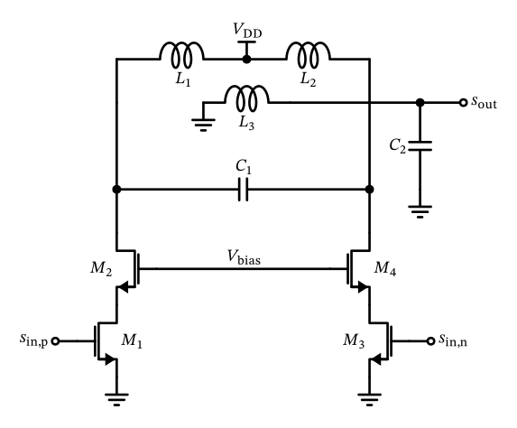
Figure 101: A generic differential power amplifier with cascode stages for peak voltage handling.

8.3 Amplifier Classes

Amplifier Classes

Table 7: Amplifier Classes
Class Conduction Angle Efficiency Linearity Description
A 360° Low High Bias current is larger than peak output current
B 180° Medium Medium Conducts half the cycle (zero bias current)
AB 180°-360° Medium Medium-high Between A and B (a little bit of bias current)
C <180° High Low Conducts less than half the cycle
D N/A Very high Low-high Switching amplifier, uses PWM or similar
E N/A Very high Low Switching amplifier with tuned load
F N/A Very high Low Uses harmonic tuning for efficiency
G N/A Very high Medium Multi-level supply voltage for efficiency
H N/A Very high Medium Adaptive supply voltage for efficiency

Amplifier Classes

  • Class A: most linear, least efficient, \(\eta \leq 50\%\)
  • Class B: half-cycle conduction, crossover distortion, \(\eta \leq 78.5\%\)
  • Class AB: compromise; linear RF PAs
  • Class C: efficient but distorting; constant-envelope modulation, \(\eta \to 100\%\) only as output power \(\to 0\)
  • Class D, E, F: switching amplifiers, very high efficiency
  • Class G, H: multiple or adaptive supply (“envelope tracking”); AB + G/H is state of the art in mobile PAs

8.4 PA Stability and Neutralization

PA Stability and Neutralization

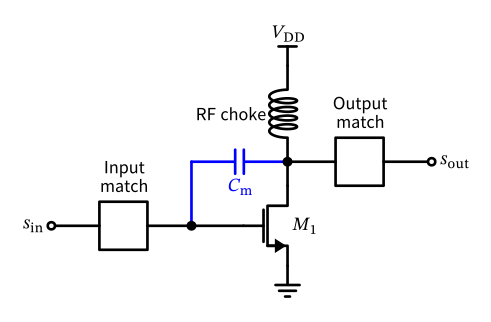
Figure 102: A basic single stage single-ended common-source power amplifier showing the Miller capacitance \(C_\mathrm{m}\) between input and output (in blue).

PA Stability and Neutralization
  • Adding a cascode stage, which isolates the input from the output and reduces the effect of \(C_\mathrm{m}\) significantly (see Figure 101).
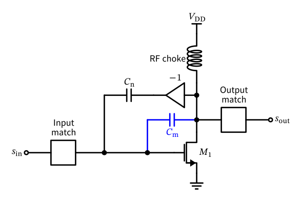
  • Adding a neutralization capacitor between the gate and drain, which cancels out the effect of \(C_\mathrm{m}\). Alternatively, feedback networks or additional circuitry can be used to stabilize the PA.

PA Stability and Neutralization

Figure 103: A basic single stage single-ended common-source power amplifier showing the Miller capacitance \(C_\mathrm{m}\) between input and output (in blue) and the neutralization capacitor \(C_\mathrm{n}\).

PA Stability and Neutralization
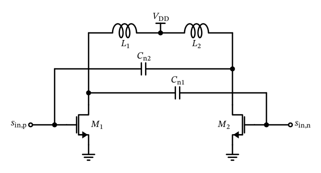
Figure 104: A generic differential power amplifier with neutralization for wideband operation and improved stability.

8.5 PA Advanced Techniques

PA Advanced Techniques

  • Predistortion (DPD): inverse distortion of the input cancels PA nonlinearity
  • Envelope tracking: supply follows the signal envelope (cf. Class G/H)
  • Load modulation: tunable or switched load; actively in the Doherty amplifier (main and peaking amplifier) for efficiency at back-off

References

Fuhrmann, J., J. Moreira, P. Oßmann, A. Springer, R. Weigel, and H. Pretl. 2017. “A 15-Bit 28nm CMOS Fully-Integrated 1.6W Digital Power Amplifier for LTE IoT.” ESSCIRC 2017 - 43rd IEEE European Solid State Circuits Conference, September, 199–202. https://doi.org/10.1109/esscirc.2017.8094560.
Moreira, José, Stephan Leuschner, Nenad Stevanovic, et al. 2015. “9.2 A Single-Chip HSPA Transceiver with Fully Integrated 3G CMOS Power Amplifiers.” 2015 IEEE International Solid-State Circuits Conference - (ISSCC) Digest of Technical Papers, February, 162–64. https://doi.org/10.1109/isscc.2015.7062976.
Saleh, A A M. 1981. “Frequency-Independent and Frequency-Dependent Nonlinear Models of TWT Amplifiers.” IEEE Transactions on Communications 29 (11): 1715–20. https://doi.org/10.1109/tcom.1981.1094911.

References