Appendix: RF Circuit Simulation
Radio-Frequency Integrated Circuits
10 Appendix: RF Circuit Simulation
Appendix: RF Circuit Simulation
- Widely separated time scales: GHz LO, kHz to MHz signal, Hz flicker noise
- Large periodic signals (LO, clock, carrier): the circuit is time-variant for the small signal (Section 5.2)
- Frequency translation of noise: modulated and folded noise
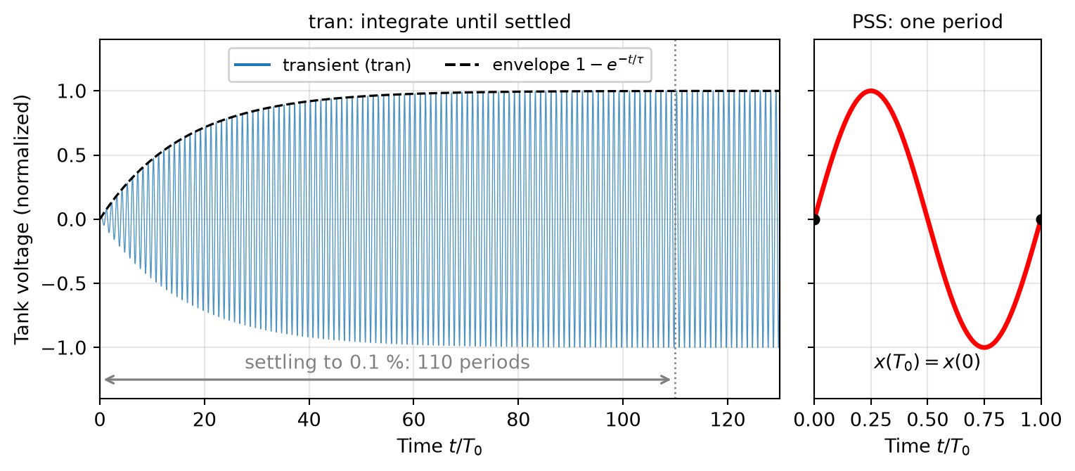
- High-Q resonators and oscillators: long settling, no stable dc operating point
Appendix: RF Circuit Simulation
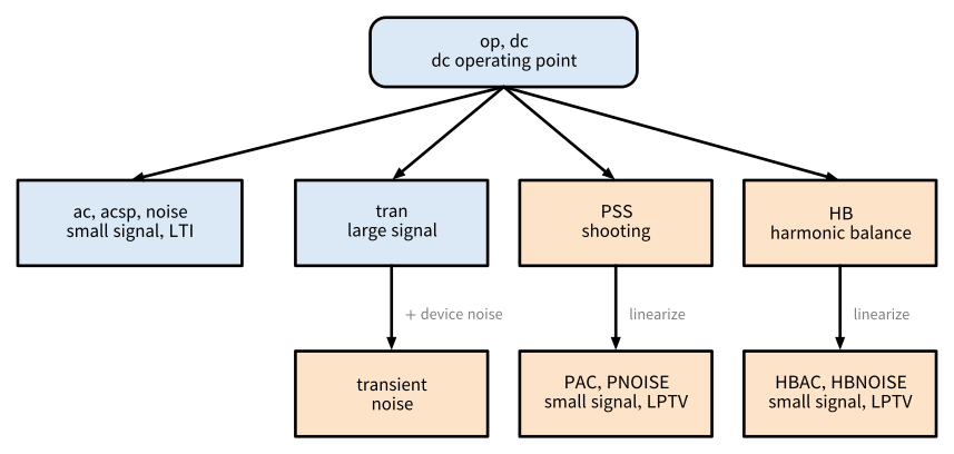
Figure 106: Family tree of circuit simulation analyses.
Appendix: RF Circuit Simulation
\[ \mathbf{f}(\mathbf{x}(t)) + \frac{\mathrm{d}}{\mathrm{d}t} \mathbf{q}(\mathbf{x}(t)) = \mathbf{u}(t), \tag{70}\]
Appendix: RF Circuit Simulation
- op: \(\mathrm{d}/\mathrm{d}t = 0\), \(\mathbf{f}(\mathbf{x}_0) = \mathbf{u}_\mathrm{DC}\)
- ac, noise: linearized around \(\mathbf{x}_0\) (LTI)
- tran: no assumption, integrate in time
- PSS, HB: \(\mathbf{x}(t + T) = \mathbf{x}(t)\)
- PAC, PNOISE, HBAC, HBNOISE: linearized around \(\mathbf{x}_\mathrm{s}(t)\) (LPTV)
10.1 Fundamental Analyses
10.1.1 DC Operating Point and DC Sweep
\[ \mathbf{G}(\mathbf{x}^{(i)}) \, \Delta \mathbf{x}^{(i)} = \mathbf{u}_\mathrm{DC} - \mathbf{f}(\mathbf{x}^{(i)}), \qquad \mathbf{x}^{(i+1)} = \mathbf{x}^{(i)} + \Delta \mathbf{x}^{(i)}, \tag{71}\]
DC Operating Point and DC Sweep
Always Check the Operating Point First
Every small-signal analysis (ac, acsp, noise) linearizes around the operating point and inherits all its errors. Check bias currents, \(g_\mathrm{m}/I_\mathrm{D}\) values, and saturation margins before looking at any other result. Note also that circuits with positive feedback (latches, oscillators) have an operating point that is an unstable equilibrium: it is a valid solution of the equations, but the real circuit never stays there.
DC Operating Point and DC Sweep
Always Check the Operating Point First
For bistable circuits, the operating point may not converge at all, and a defined state (a reset or a nodeset) helps.
10.1.2 Small-Signal AC Analysis
\[ \left( \mathbf{G} + j \omega \mathbf{C} \right) \mathbf{X}(j\omega) = \mathbf{U}(j\omega), \qquad \mathbf{G} = \frac{\partial \mathbf{f}}{\partial \mathbf{x}}, \quad \mathbf{C} = \frac{\partial \mathbf{q}}{\partial \mathbf{x}}, \tag{72}\]
10.1.3 S-Parameter Analysis
\[ a_i = \frac{V_i + Z_0 I_i}{2 \sqrt{Z_0}}, \quad b_i = \frac{V_i - Z_0 I_i}{2 \sqrt{Z_0}}, \quad S_{ij} = \frac{b_i}{a_j} \quad (a_k = 0 \text{ for } k \neq j). \tag{73}\]
10.1.4 Small-Signal Noise Analysis
\[ S_\mathrm{out}(f) = \sum_i \left| H_i(f) \right|^2 S_i(f), \tag{74}\]
10.1.5 Transient Analysis
\[ \mathbf{f}(\mathbf{x}_{n+1}) + \frac{\mathbf{q}(\mathbf{x}_{n+1}) - \mathbf{q}(\mathbf{x}_n)}{h_n} = \mathbf{u}(t_{n+1}), \tag{75}\]
Transient Analysis
- Cost: step size set by the fastest signal, simulated time by the slowest effect
- Numerical artifacts: trapezoidal ringing, Gear damping, so always set a maximum time step that resolves the carrier
- Spectral analysis: needs steady state, coherent sampling or windowing, and tight tolerances
Transient Analysis
Note 9: Transient Simulation Effort of a Mixer
We want to simulate the conversion gain of a downconversion mixer with \(f_\mathrm{LO} = 2.4\,\text{GHz}\) and an IF around 1 MHz, with a frequency resolution of 10 kHz. The simulated time must be at least
\[ T_\mathrm{sim} \geq \frac{1}{10\,\text{kHz}} = 100\,\mu\text{s}. \]
With 50 time points per LO period, the step size is \(h = 1 / (50 \cdot 2.4\,\text{GHz}) \approx 8.3\,\text{ps}\), and we need
\[ N = \frac{T_\mathrm{sim}}{h} = 100\,\mu\text{s} \cdot 50 \cdot 2.4\,\text{GHz} = 1.2 \cdot 10^{7} \]
Transient Analysis
Transient Simulation Effort of a Mixer
time points, each requiring a Newton solve of the full circuit, and this excludes the settling time. A PSS analysis of the same mixer integrates only a few tens of LO periods (\(10^3\) to \(10^4\) time points, depending on the time resolution per period), and the conversion gain then follows from a PAC analysis with one linear solve per IF frequency (Section 10.2.4).
10.1.6 Comparison of the Fundamental Analyses
| Analysis | Solves | Assumption | Typical RF use |
|---|---|---|---|
op, dc sweep |
\(\mathbf{f}(\mathbf{x}_0) = \mathbf{u}_\mathrm{DC}\) | static | bias point, dc transfer curves |
ac |
Equation 72 | small signal, LTI | gain, bandwidth, impedances, loop gain |
acsp |
Equation 72 with ports | small signal, LTI | matching, gain, isolation, stability, passives |
noise |
Equation 74 | small signal, stationary noise | NF of LNAs and baseband, noise contributions |
tran |
Equation 75 | none | start-up, settling, switching, large-signal reference |
10.2 Advanced RF Analyses
Advanced RF Analyses
- Large-signal step. The periodic steady state is computed directly, either in the time domain (shooting PSS, Section 10.2.2) or in the frequency domain (HB, Section 10.2.3), without simulating the settling transient.
- Small-signal step. The circuit is linearized around this periodic steady state. The resulting LPTV system is analyzed for frequency-translating transfer functions (PAC, HBAC, Section 10.2.4) and for cyclostationary noise (PNOISE, HBNOISE, Section 10.2.5).
10.2.1 Transient Noise
- Statistics: one realization per run, so long records, many seeds, resolution \(1/T_\mathrm{sim}\)
- Run time: step size limited by \(f_\mathrm{max}\)
- Band limits: flicker needs \(T_\mathrm{sim} \gg 1/f_\mathrm{min}\), resample finely before a PSD
- Numerical artifacts: run at reduced noise amplitudes, keep the part that scales with the amplitude squared
- Clocked circuits: complete all needed decisions, validate independently
10.2.2 Periodic Steady State by Shooting (PSS)
\[ \boldsymbol{\phi}_T(\mathbf{x}_0) - \mathbf{x}_0 = \mathbf{0}. \tag{76}\]
\[ \left( \mathbf{\Phi}_T - \mathbf{I} \right) \Delta \mathbf{x}_0 = \mathbf{x}_0 - \boldsymbol{\phi}_T(\mathbf{x}_0), \qquad \mathbf{\Phi}_T = \frac{\partial \boldsymbol{\phi}_T}{\partial \mathbf{x}_0}, \tag{77}\]
Periodic Steady State by Shooting (PSS)
Periodic Steady State by Shooting (PSS)
PSS Does Not Prove Start-Up
PSS finds a periodic solution, but it does not tell whether the circuit actually reaches it after power-up. Whether an oscillator starts reliably over all corners (or whether a divider locks into the intended mode) must still be checked with a transient analysis.
10.2.3 Harmonic Balance (HB)
\[ \mathbf{x}(t) = \sum_{k=-K}^{K} \mathbf{X}_k \, e^{j k \omega_0 t}, \qquad \mathbf{X}_{-k} = \mathbf{X}_k^{*}, \tag{78}\]
\[ \mathbf{F}_k(\mathbf{X}) + j k \omega_0 \, \mathbf{Q}_k(\mathbf{X}) = \mathbf{U}_k, \qquad k = -K, \ldots, K. \tag{79}\]
Harmonic Balance (HB)
- Linear and distributed elements: exact, including S-parameter data
- High-Q circuits: no settling problem
- Mildly nonlinear circuits: few harmonics, very efficient (\(P_\mathrm{1dB}\), IP3, blockers)
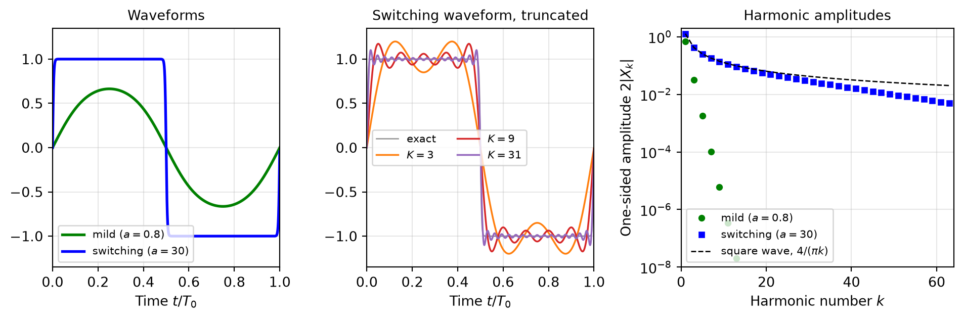
- Sharp edges: many harmonics, ill-conditioning, Gibbs ringing (Figure 108), may not converge, so use PSS
- Convergence: ramp the drive level (source stepping, sweeps)
Harmonic Balance (HB)
Harmonic Balance (HB)
| Property | PSS (shooting) | HB |
|---|---|---|
| Domain | time | frequency (devices evaluated in time) |
| Unknowns | initial state \(\mathbf{x}_0\) | Fourier coefficients \(\mathbf{X}_k\) |
| Sharp edges, switching | well suited | many harmonics, may not converge |
| Mildly nonlinear | well suited | very efficient |
| Distributed elements, S-parameter data | need a time-domain model | exact (simulator-dependent) |
| Several incommensurate large tones | not possible | well suited |
| High-Q, long settling | efficient | efficient |
| Oscillators | autonomous PSS | autonomous HB (simulator-dependent) |
| Small-signal and noise analyses | PAC, PNOISE | HBAC, HBNOISE |
10.2.4 Periodic Small-Signal Analysis (PAC, HBAC)
\[ \mathbf{G}(t) \, \Delta \mathbf{x}(t) + \frac{\mathrm{d}}{\mathrm{d}t} \left[ \mathbf{C}(t) \, \Delta \mathbf{x}(t) \right] = \Delta \mathbf{u}(t). \tag{80}\]
\[ \sum_{l=-K}^{K} \left[ \mathbf{G}_{k-l} + j (\omega + k \omega_0) \, \mathbf{C}_{k-l} \right] \Delta \mathbf{X}_l = \Delta \mathbf{U}_k, \qquad k = -K, \ldots, K, \tag{81}\]
Periodic Small-Signal Analysis (PAC, HBAC)
Periodic Small-Signal Analysis (PAC, HBAC)
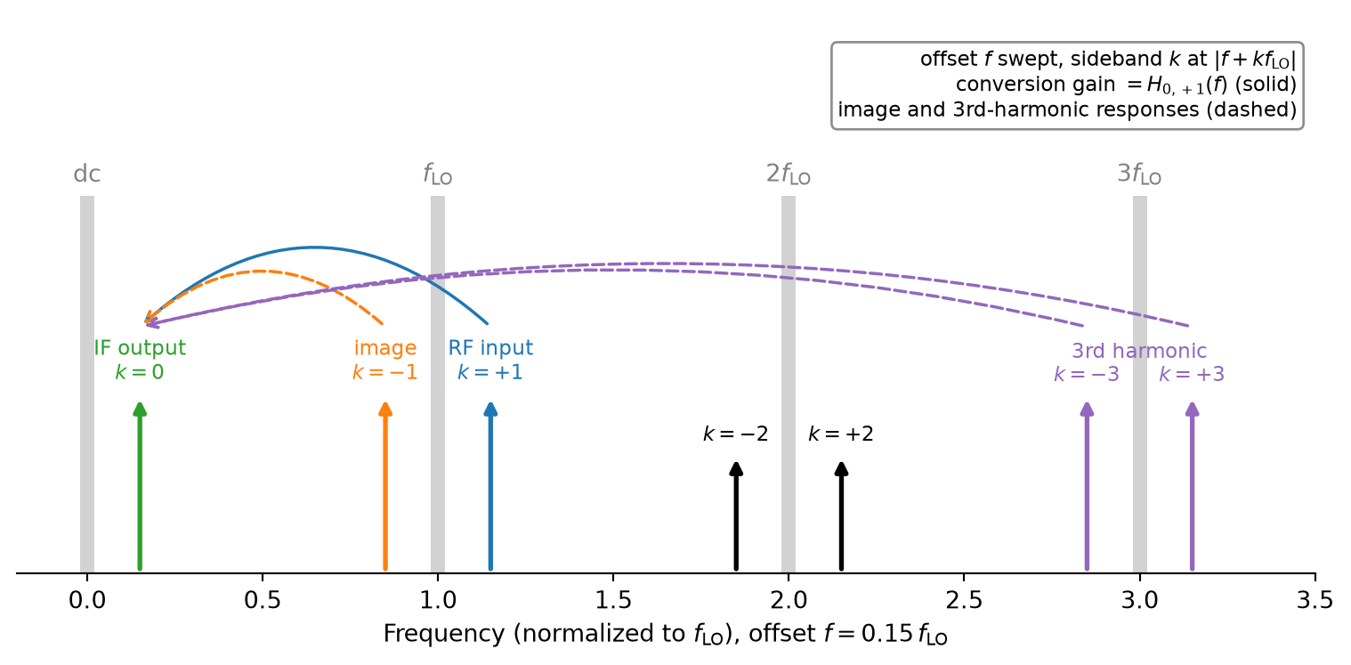
- Conversion gain: \(H_{0,+1}(f)\), RF at \(f_\mathrm{LO} + f\) to IF at \(f\)
- Image response: \(H_{0,-1}(f)\)
- Harmonic responses: \(H_{0,\pm 3}(f)\), interferers around \(3 f_\mathrm{LO}\)
- Upconversion: input at sideband \(0\), output at \(\pm 1\)
Periodic Small-Signal Analysis (PAC, HBAC)
Why an AC Analysis of a Mixer Fails
An ac analysis linearizes around the dc operating point, where the LO source sits at its dc value. The mixer is “frozen” in one LO state, the circuit is LTI, and no frequency conversion takes place: the ac analysis shows at most a feedthrough at the RF frequency, but no IF output. Frequency-converting circuits need PAC or HBAC.
Periodic Small-Signal Analysis (PAC, HBAC)
- SC filters, sampling circuits: transfer including aliasing
- N-path filters, passive mixers: input impedance around \(f_\mathrm{LO}\) (Equation 53)
- Power detectors: video response
- Amplifiers under a blocker: desensitization (Equation 11)
- Chopper amplifiers: gain after demodulation, ripple at the chopping harmonics
10.2.5 Periodic Noise Analysis (PNOISE, HBNOISE)
- Modulation. The noise sources depend on the time-varying operating point: channel thermal noise follows the channel conductance (see Section 2.3.1), shot noise follows the current \(I(t)\), and flicker noise depends on the bias as well. Such a source can be written as \(n_i(t) = m_i(t) \, w_i(t)\), with a stationary noise process \(w_i(t)\) and a periodic modulation \(m_i(t)\). Its statistics vary periodically with time, so the noise is cyclostationary.
Periodic Noise Analysis (PNOISE, HBNOISE)
- Frequency translation. The LPTV transfer of Equation 81 moves noise from all sidebands \(f + l f_0\) to the output frequency \(f\), which is called noise folding.
Periodic Noise Analysis (PNOISE, HBNOISE)
\[ S_\mathrm{out}(f) = \sum_i \sum_{l} \left| \sum_{k} H_{i,k}(f) \, M_{i,k-l} \right|^2 S_i(f + l f_0), \tag{82}\]
Periodic Noise Analysis (PNOISE, HBNOISE)
Note 10: Noise Folding in an Ideal Switching Mixer
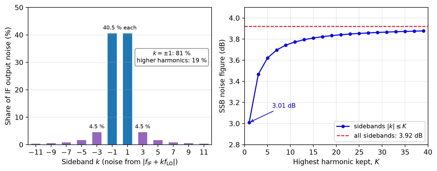
An ideal double-balanced switching mixer multiplies the RF input by a square wave toggling between \(+1\) and \(-1\) with 50% duty cycle (see Section 5.2), whose Fourier coefficients have the magnitude \(|c_k| = 2/(\pi |k|)\) for odd \(k\) and vanish for even \(k\). The switches are noiseless, and the only noise is the white thermal noise of the source resistance, with the PSD \(S_\mathrm{n}\) at every frequency. The noise from each sideband \(k\) folds to the IF with the weight \(|c_k|^2\).
Periodic Noise Analysis (PNOISE, HBNOISE)
Noise Folding in an Ideal Switching Mixer
By Parseval’s theorem, the sum of all weights equals the time average of the squared switching function, which is one:
\[ S_\mathrm{out} = S_\mathrm{n} \sum_{k} |c_k|^2 = S_\mathrm{n}. \]
The wanted RF signal at sideband \(+1\) is converted with the power gain \(|c_1|^2 = 4/\pi^2\). In the single-sideband (SSB) noise factor, only the source noise at the signal frequency counts as input noise, hence
\[ F_\mathrm{SSB} = \frac{S_\mathrm{out}}{|c_1|^2 S_\mathrm{n}} = \frac{\pi^2}{4} \approx 3.9\,\text{dB}. \]
Periodic Noise Analysis (PNOISE, HBNOISE)
Noise Folding in an Ideal Switching Mixer
If the signal occupies both sidebands \(\pm 1\) (as in a direct-conversion receiver), the source noise of both counts as input noise, and the double-sideband (DSB) noise factor is \(F_\mathrm{DSB} = \pi^2/8 \approx 0.9\,\text{dB}\), i.e., 3 dB lower. An analysis that keeps only the sidebands \(\pm 1\) (\(K = 1\)) would miss the 19 % of the noise folded from around \(3 f_\mathrm{LO}\), \(5 f_\mathrm{LO}\), and so on, and underestimate the SSB noise figure by 0.9 dB (3.0 dB instead of 3.9 dB, see Figure 110).
Periodic Noise Analysis (PNOISE, HBNOISE)
Periodic Noise Analysis (PNOISE, HBNOISE)
- Mixers: SSB/DSB NF incl. image and harmonic folding, LO-translated flicker noise
- Sampling, SC circuits: \(kT/C\) noise from folded wideband noise
- Power detectors: noise with the LO or carrier applied
- Amplifiers under a blocker: blocker noise figure
- Chopper amplifiers: residual flicker noise, white noise folded from the chopping harmonics
- Oscillators: phase noise incl. \(1/f^3\) region from periodic noise (valid down to where numerical errors pin the phase, check the \(1/f^2\) slope) or transient noise, but never from a plain noise analysis
Periodic Noise Analysis (PNOISE, HBNOISE)
Note 11: Example: Phase Noise of an LC Oscillator in VACASK
A parallel LC tank at \(f_0 = 1\) GHz (\(R_\mathrm{p} = 500\,\Omega\), \(C = 10\) pF, \(Q = 31\)), whose loss is compensated by a noiseless negative conductance \(i = -g_1 v + g_3 v^3\) (Van der Pol), oscillates with \(V_\mathrm{p} = 1\) V. The tank resistance is then the only noise source, and the phase noise follows Equation 57 with \(F = 1\), e.g., \(-126.8\) dBc/Hz at 100 kHz offset. VACASK’s pnoise around the autonomous PSS (pss with oscillator=1) reproduces it within 0.02 dB from 10 kHz to 1 MHz, but only with a fine enough time step.
Periodic Noise Analysis (PNOISE, HBNOISE)
Example: Phase Noise of an LC Oscillator in VACASK
With the default settings, the result flattens below about 20 kHz (\(f_0/50\,000\)) and is already 7.5 dB too low at 10 kHz. The corner depends neither on the number of harmonics (truncharm from 5 to 80 gives the same result) nor on the tolerances, but on the time step with which pnoise integrates the period that it samples for the conversion matrix.
Periodic Noise Analysis (PNOISE, HBNOISE)
Example: Phase Noise of an LC Oscillator in VACASK
Four times as many points per period (pss_minpts) move it four times lower, and limiting the time step between the sampling points (options tran_fbr=0.02 before the pnoise analysis) moved it below 1 kHz, i.e., \(f_0/10^6\). All numbers are from the VACASK version of the IIC-OSIC-TOOLS container 2026.10.
10.3 Choosing the Right Analysis
Choosing the Right Analysis
| Analysis | Builds on | Linearized | Captures | Main limitation |
|---|---|---|---|---|
| transient noise | tran | no | in principle everything: switching, folding, jitter, decisions | statistics, run time, numerical artifacts |
| PSS | shooting (time) | no | periodic steady state, harmonics, oscillation frequency | one common period |
| HB | Fourier series | no | (quasi-)periodic steady state, IM products | many harmonics for sharp edges |
| PAC, HBAC | PSS, HB | yes (LPTV) | conversion gain, sideband transfer, aliasing | small signals only |
| PNOISE, HBNOISE | PSS, HB | yes (LPTV) | cyclostationary noise, folding, mixer NF | small noise only |
Choosing the Right Analysis
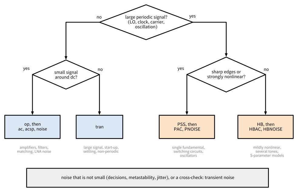
Figure 111: Choosing an analysis.
Choosing the Right Analysis
| Circuit | Key metrics | Recommended analyses |
|---|---|---|
| LNA | match, gain, NF, stability, \(P_\mathrm{1dB}\), IIP3, blocker NF | op, acsp and noise, HB for \(P_\mathrm{1dB}\) and two-tone IIP3, HBAC and HBNOISE with a blocker |
| Mixer | conversion gain, SSB/DSB NF, IIP3, image and harmonic rejection | PSS (hard-switching LO) or HB, PAC or HBAC, PNOISE or HBNOISE, two-tone HB for IIP3 |
| Oscillator, VCO | start-up, frequency, tuning range, phase noise | tran for start-up, autonomous PSS, transient noise or periodic noise around the autonomous PSS (simulator-dependent) |
| SC circuits, sampling, N-path | transfer incl. aliasing, settling, \(kT/C\) noise | tran, PSS, PAC and PNOISE if they converge in \(K\) (not HB), transient noise |
Choosing the Right Analysis
| Circuit | Key metrics | Recommended analyses |
|---|---|---|
| Power detector | responsivity, compression, video bandwidth, NEP, NF | HB or PSS power sweep, HBAC or PAC, noise with the LO off, HBNOISE or PNOISE with the LO on, transient noise |
| Power amplifier | output power, efficiency, AM/AM, AM/PM, harmonics | HB power sweep (with EM models of the matching network), PSS for switching PAs, tran |
| Divider, LO generation | operating range, duty cycle, I/Q phase error, jitter | tran, PSS, PNOISE or transient noise for jitter |
| Chopper amplifier | gain, ripple, residual flicker noise | tran, PSS with PAC and PNOISE |
| Comparator, latch | offset, noise, metastability | tran, transient noise |
Choosing the Right Analysis
| Circuit | Key metrics | Recommended analyses |
|---|---|---|
| Passives | Q, S-parameters | acsp with EM-derived models |
Choosing the Right Analysis
- Convergence parameters: harmonics, time step, tolerances, stabilization time, also at the highest drive
- Independent methods: HB vs. PSS, PAC vs. HBAC, PNOISE vs. HBNOISE, PAC vs. two-tone tran, PNOISE vs. transient noise, PNOISE without large signal vs. noise
- Simulator messages: a finished run is not a correct one
Choosing the Right Analysis
Note 12: Example: A 160 GHz Power Detector
The open-source SPARX receiver (Dorrer et al. 2026) contains a Schottky-diode power detector at 160 GHz, characterized with VACASK as a mixer with a 159 GHz LO. Its testbenches use most of the analyses of this appendix:
Choosing the Right Analysis
Example: A 160 GHz Power Detector
- HB power sweep for the transfer curve (responsivity and compression), cross-checked with PSS at nine drive levels. The two agree within 1.2 % over an input range of 80 dB.
- HBAC for the conversion gain of each sideband to the IF and the video bandwidth, cross-checked with PAC (within 0.03 dB).
Choosing the Right Analysis
Example: A 160 GHz Power Detector
- noise (LO off) and HBNOISE (LO on) for the noise figure: the LO raises the output noise, so the noise analysis at the dc operating point is 1.2 dB to 2.6 dB optimistic over the IF band, and far more at high LO drive. PNOISE reproduces HBNOISE within 0.2 dB.
- Transient noise with the LO on, run at reduced noise amplitudes and reduced to its linear part, agrees with HBNOISE within about 1 dB.
10.4 Simulator Support
Simulator Support
| Analysis | VACASK (container 2026.10) | ngspice 47 |
|---|---|---|
| dc operating point, dc sweep | op, op inside a sweep |
.op, .dc |
| ac | ac |
.ac |
| S-parameters | acsp |
.sp |
| noise | noise |
.noise |
| transient | tran |
.tran |
| transient noise | tran with noisefmax (device noise) |
.tran with trnoise sources |
| PSS | pss (driven and autonomous) |
.pss (experimental, autonomous only) |
| HB | hb (single and multi-tone) |
not available |
| PAC, PNOISE | pac, pnoise |
not available |
| HBAC, HBNOISE | hbac, hbnoise |
not available |
Simulator Support
// LO: large-signal sine, RF: small-signal tone at sideband +1 (f_LO + f)
vlo (lo 0) vsource type="sine" sinedc=0 ampl=0.5 freq=2.4G
vrf (rfs 0) vsource dc=0 spur={1} smag=[1]
rs (rfs rf) resistor r=50

control
  var flo=2.4G
  analysis op1 op
  // large signal: periodic steady state with the LO, stored for reuse
  analysis pss1 pss tper=1/flo tstab=20/flo store="lo_ss"
  // conversion gain from the RF (sideband +1) to the IF (sideband 0)
  analysis pac1 pac ( ic="lo_ss" psssolve=0 truncharm=40 outharm=0
                      from=100k to=100M mode="dec" points=10 )
  // output noise at the IF, gain from the RF at sideband +1 (SSB NF)
  analysis pn1 pnoise ( ic="lo_ss" psssolve=0 truncharm=40
                        in="vrf" inharm=1 out="out" outharm=0
                        from=100k to=100M mode="dec" points=10 )
endc10.5 Summary
Summary
Key Takeaways
- op, ac, acsp, noise linearize around a constant operating point: fast and insightful, but blind to distortion, frequency conversion, and noise folding.
- tran is the general reference, but RF time scales make it expensive, and a maximum time step is mandatory.
- PSS (time domain) and HB (frequency domain) find the periodic steady state directly. PSS suits switching circuits and oscillators, HB mildly nonlinear and multi-tone problems and circuits with distributed elements.
Summary
Key Takeaways
- PAC, HBAC and PNOISE, HBNOISE linearize around this steady state (LPTV) and give conversion gain, aliasing, and cyclostationary noise including folding.
- Transient noise captures everything in principle, at a high cost and with numerical pitfalls. Run at reduced noise amplitude, it is an independent cross-check.
- Increase harmonics, tighten time steps, and compare independent methods before trusting a result.
References
Aprille, T. J., and T. N. Trick. 1972. “Steady-state analysis of nonlinear circuits with periodic inputs.” Proceedings of the IEEE 60 (1): 108–14. https://doi.org/10.1109/PROC.1972.8563.
Bűrmen, Árpád. 2025. VACASK – a novel analog integrated circuit simulator. 60th International Conference on Microelectronics, Devices and Materials (MIDEM 2025), Ljubljana, Slovenia. https://doi.org/10.5281/zenodo.17434615.
Demir, A., A. Mehrotra, and J. Roychowdhury. 2000. “Phase noise in oscillators: a unifying theory and numerical methods for characterization.” IEEE Transactions on Circuits and Systems I: Fundamental Theory and Applications 47 (5): 655–74. https://doi.org/10.1109/81.847872.
Dorrer, Simon, David Kellerer-Pirklbauer, and Harald Pretl. 2026. GitHub Repository for SPARX: An Open-Source, Automated, Programmatically Generated, Frequency-Scalable Six-Port Receiver in 130-nm CMOS. https://doi.org/10.5281/zenodo.19654232.
Hajimiri, A., and T. H. Lee. 1998. “A general theory of phase noise in electrical oscillators.” IEEE Journal of Solid-State Circuits 33 (2): 179–94. https://doi.org/10.1109/4.658619.
Kundert, K. S. 1999. “Introduction to RF simulation and its application.” IEEE Journal of Solid-State Circuits 34 (9): 1298–319. https://doi.org/10.1109/4.782091.
Nagel, Laurence W. 1975. SPICE2: A Computer Program to Simulate Semiconductor Circuits. Memorandum ERL-M520. Electronics Research Laboratory, University of California, Berkeley.
Nakhla, M., and J. Vlach. 1976. “A piecewise harmonic balance technique for determination of periodic response of nonlinear systems.” IEEE Transactions on Circuits and Systems 23 (2): 85–91. https://doi.org/10.1109/TCS.1976.1084181.
Okumura, M., H. Tanimoto, T. Itakura, and T. Sugawara. 1993. “Numerical noise analysis for nonlinear circuits with a periodic large signal excitation including cyclostationary noise sources.” IEEE Transactions on Circuits and Systems I: Fundamental Theory and Applications 40 (9): 581–90. https://doi.org/10.1109/81.244907.
Pozar, David M. 2011. Microwave Engineering. 4th edition. Wiley.
Razavi, Behzad. 2020. “The Design of a Comparator [The Analog Mind].” IEEE Solid-State Circuits Magazine 12 (4): 8–14. https://doi.org/10.1109/MSSC.2020.3021865.
Roychowdhury, J., D. Long, and P. Feldmann. 1998. “Cyclostationary noise analysis of large RF circuits with multitone excitations.” IEEE Journal of Solid-State Circuits 33 (3): 324–36. https://doi.org/10.1109/4.661198.
Telichevesky, Ricardo, Kenneth S. Kundert, and Jacob K. White. 1995. “Efficient steady-state analysis based on matrix-free Krylov-subspace methods.” Proceedings of the 32nd ACM/IEEE Design Automation Conference (DAC), 480–84. https://doi.org/10.1145/217474.217574.