Introduction
Radio-Frequency Integrated Circuits
1 Introduction
Introduction
Important
All course material (source code of this document, Jupyter notebooks for calculations, etc.) is made publicly available on GitHub (follow this link) and shared under the Apache-2.0 license.
Please feel free to submit pull requests to fix typos or add content! If you want to discuss something that is not clear, please open an issue.
1.1 Wireless Transmission
Wireless Transmission

Figure 1: The block diagram of a simple wireless system.
Wireless Transmission
- The wireless channel is shared between all users.
- As a consequence, the available bandwidth is shared; this means that bandwidth is a scarce resource.
- The wireless channel has significant losses.
- The channel is time variant, as usually the transmitter and/or the receiver move, and/or the environment changes.
Wireless Transmission
\[ P_\mathrm{R} = \frac{P_\mathrm{T} \cdot G_\mathrm{T}}{4 \pi d^2} \cdot A_\mathrm{R} = P_\mathrm{T} \cdot \frac{A_\mathrm{R} \cdot A_\mathrm{T}}{d^2 \lambda^2} \tag{1}\]
\[ G = \frac{4 \pi A}{\lambda^2}, \tag{2}\]
Wireless Transmission
\[ A \propto \lambda^2 \]
\[ c = \lambda f. \]
Wireless Transmission
| Application | Frequency | Wavelength |
|---|---|---|
| FM Radio | 88 MHz to 108 MHz | 3.4 m down to 2.8 m |
| WiFi (lowband) | 2.4 GHz | 12.5 cm |
| WiFi (highband) | 5 GHz | 6 cm |
| Bluetooth | 2.4 GHz | 12.5 cm |
| Cellular | 0.6 GHz to 5 GHz | 50 cm down to 6 cm |
| GNSS | 1.575 GHz | 19 cm |
Wireless Transmission
Note 1: Wavelength Calculation
Let’s calculate the wavelength for a Bluetooth signal at 2.4 GHz. Given:
- Frequency \(f = 2.4\,\text{GHz} = 2.4 \times 10^9\,\text{Hz}\)
- Speed of light \(c = 3 \times 10^8\,\text{m/s}\)
Using the relationship \(c = \lambda f\), we can solve for wavelength:
\[\lambda = \frac{c}{f} = \frac{3 \times 10^8\,\text{m/s}}{2.4 \times 10^9\,\text{Hz}} = 0.125\,\text{m} = 12.5\,\text{cm}\]
This means that a quarter-wavelength monopole antenna for 2.4 GHz Bluetooth would be approximately 3.1 cm long, which easily fits into most mobile devices.
Wireless Transmission
\[ P|_\text{dBm} = 10 \cdot \log_{10} \left( \frac{P|_\text{W}}{1\,\text{mW}} \right) \tag{3}\]
Wireless Transmission
Note 2: Wireless Transmission
We use the following parameters:
- Transmit power \(P_\mathrm{T} = 1\,\text{W}\)
- Frequency \(f = 2.4\,\text{GHz}\)
- Communication distance \(d = 10\,\text{km}\)
- Using \(\lambda/2\) dipoles on both ends
Using Equation 1 we calculate
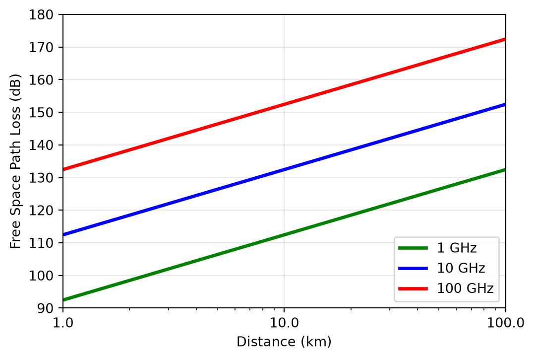
\[ P_\mathrm{R} = P_\mathrm{T} \cdot \frac{0.13 \lambda^2 \cdot 0.13 \lambda^2}{d^2 \lambda^2} = P_\mathrm{T} \cdot 0.13^2 \left( \frac{\lambda}{d} \right)^2 = 2.64\,\text{pW} = -85.8\,\text{dBm} \]
With the transmit power of 1 W = 30 dBm we have an attenuation of 116 dB! This is a very large number!
Wireless Transmission
\[ \text{FSPL} = 20 \cdot \log_{10}(d / \text{m}) + 20 \cdot \log_{10}(f / \text{Hz}) + 20 \cdot \log_{10} \left( \frac{4\pi}{c} \text{m/s} \right). \tag{4}\]
Wireless Transmission
Wireless Transmission
- The given attenuation is for line-of-sight paths; often, the attenuation is significantly higher than this due to blockage by buildings, mountains, rain, or foliage.
- In the absence of a direct line-of-sight path, the EM wave is redirected by reflections, causing additional attenuation and potential destructive interference due to multi-path reception.
Wireless Transmission
- TX: enough transmit power at high efficiency
- RX: process weak signals with low noise
- RX: tolerate large interfering signals (blockers)
- Pack information into a small bandwidth
- Battery operation: minimum power consumption
1.2 Wireless Standards
Wireless Standards
| Standard | GSM (2G) | WCDMA (3G) | LTE (4G) 5G NR |
WiFi | Bluetooth | GNSS |
|---|---|---|---|---|---|---|
| Frequency range (MHz) | 850, 900, 1800, 1900 | 850, 900, 1700, 1900, 2100 | Multiple bands 450…7100 (FR1), 24000…48000 (FR2) | 2400, 5000, 6000 | 2400 | 1500, 1200 |
| Modulation | GMSK, 8PSK (EDGE) | QPSK (DL), BPSK (UL), 16QAM (HSPA), 64QAM (HSPA) | QPSK, 16QAM, 64QAM (DL+UL) 256QAM (DL+UL) | BPSK, QPSK, 16QAM, 64QAM, 256QAM, 1024QAM, 4096QAM | GFSK (m=0.28…0.35), \(\pi\)/4-DQPSK, 8DPSK | BPSK, QPSK |
| Transmission/ multiple access | TDMA, FDMA | DS-CDMA | OFDMA (DL+UL), SC-FDMA/DFT-s-OFDM (UL) | OFDM, CSMA/CA | FHSS | CDMA |
| Duplex | FDD | FDD | FDD, TDD | TDD | TDD | n/a |
Wireless Standards
| Standard | GSM (2G) | WCDMA (3G) | LTE (4G) 5G NR |
WiFi | Bluetooth | GNSS |
|---|---|---|---|---|---|---|
| Channel bandwidth | 200 kHz | 5 MHz | 1.4, 3, 5, 10, 15, 20, …, 100 MHz (FR1), 400 MHz (FR2) | 10, 20, 40, 80, 160, 320 MHz | 1 MHz | 16…24 MHz |
| Symbol rate1 | 270.833 ksym/s | 3.84 Msym/s | 15/30/60 ksym/s | 312.5 ksym/s (11a/g/n/ac), 78.125 ksym/s (11ax/be) | 1 Msym/s | 50 sym/s |
| Pulse shaping | Gaussian (BT=0.3) | Root Raised Cosine (\(\alpha\)=0.22) | Rectangular | Rectangular | Gaussian (BT=0.5) | Rectangular |
Wireless Standards
| Standard | GSM (2G) | WCDMA (3G) | LTE (4G) 5G NR |
WiFi | Bluetooth | GNSS |
|---|---|---|---|---|---|---|
| Transmit power | 1…2 W | 250 mW | 200 mW (FDD), 400 mW (TDD) | 100 mW | 1…100 mW | n/a |
| PAR (UL) | 0 dB (GMSK), 3 dB (8PSK) | 3…8 dB | 6…8 dB | Up to 12 dB | 0 dB (GFSK), 3 dB (8DPSK) | n/a |
| MIMO | no | Not realized (DL 2x2) | DL 4x4 (up to 8x8) | 2x2 (up to 8x8) | no | no |
| Channel bond | no | Up to 4x5 MHz | Up to 7x20/4x100 MHz | Up to 80+80+80+80 MHz | no | no |
Wireless Standards
Wireless Standards
References
Balanis, Constantine A. 2005. Antenna Theory: Analysis and Design. Wiley-Interscience.
Darabi, Hooman. 2020. Radio Frequency Integrated Circuits and Systems. 2nd edition. Cambridge University Press.
Pozar, David M. 2011. Microwave Engineering. 4th edition. Wiley.
Razavi, Behzad. 2011. RF Microelectronics. 2nd edition. Pearson.